
Contributed by Sven G on from the it's supposed to be fish, not dogs dept.
We received a contribution from Sven G, about checking the temperature in the garage where his dog sleeps with OpenBSD:
I was inspired by the April 2017 article in undeadly.org about getting OpenBSD running on a Raspberry Pi 3B+. My goal was to use a Raspberry Pi running OpenBSD to monitor the temperature in my garage from my home. My dog has his own little "apartment" inside the garage, so I want to keep an eye on the temperature. (I don't rely on this device. He sleeps inside the house whenever he wants.)
If anything seems wrongheaded, please chalk it up to a frothy mixture of enthusiasm, ignorance, stubbornness, and "just-because-I-wanted-to-do-it-this-way-ness."
I bought a TemperHum USB sensor, but it might have been defective. It locked up my Pi whenever I plugged it in. However, I had a cheap DHT22 temperature sensor and an Arduino Mega 2560 lying around.
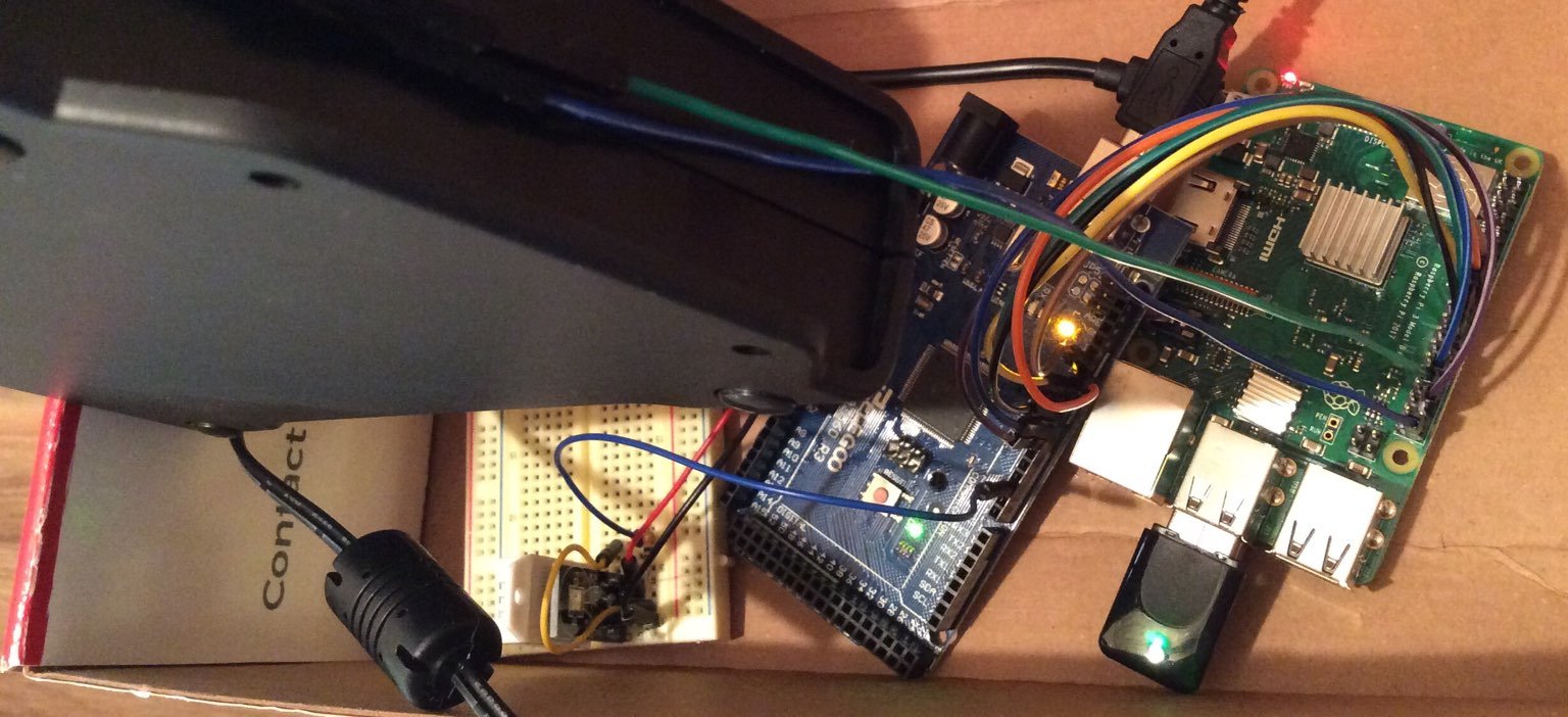
Here is the setup: A Pi called "Talker" is in the garage, along with the Arduino. The Arduino reads the temperature from the DHT22 and converts it to a binary number and writes that number to seven digital pins. Let's call the pins pin64, pin32, pin16, pin8, pin4, pin2, and pin1. We connect those pins to the corresponding GPIO pins on Talker.
Talker runs a daemon called gpiotalker. The daemon reads the GPIO pins, converts the binary number back to an integer, and sends out the temperature as an integer at regular intervals over UDP.
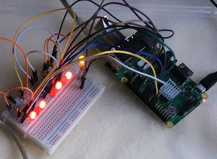
Talker has a VPN connection to the Raspberry Pi called "Listener" in my home. Listener runs a daemon called gpiolistener. The daemon reads the integer coming over the UDP connection, converts it to binary, and writes out to seven GPIO pins connected to LEDs, representing the pin64, pin32, pin16, pin8, pin4, pin2, and pin1. That way I can look at the lights and see the temperature displayed as a binary number. There is an additional alert pin that lights up if the temperature is outside a given range.
Since I'm using OpenBSD, I can use a secure, easy-to-use VPN as described on the OpenBSD FAQ. OpenBSD also lets me easily add security features to the daemons. One example is being able to run the daemons as unprivileged users. (I tried using pledge, but my guess is that the necessary ioctl permissions are not available for accessing the GPIO pins, based on my reading of "man pledge" and the tty section.)
In my particular setup, I use an access point that is not connected to the Internet. However, one could obviously easily do so, and create a simple web interface. It might also be possible, depending on the number of pins available, to also monitor humidity or other things such as formaldehyde levels, depending on the sensor attached to the Arduino. Instead of having the alert pin light up a LED, I could attach a relay and then power up a big lamp or radio or something like that if I really wanted it to get my attention.
Below I will describe how I set everything up.
Networking
The Raspberry Pi I call Talker uses a USB wireless device using the urtwn firmware which I obtained using /usr/sbin/fw_update. To initially get the Raspberry Pi on the Internet, I used a USB-to-Ethernet device running the axe firmware, which worked from the default installation.
The Raspberry Pi I call Listener is connected directly to a cheap wireless access point through its Ethernet port.
Putting OpenBSD on a Raspberry Pi
You need a USB to TTL serial cable, an SD card to boot from with the install media, and a USB drive attached to the Raspberry Pi which you will install OpenBSD onto. Please see the undeadly. org article that started it all for me.
To install on the Raspberry Pi 3B+, you do not need any special u-boot stuff as you would for, say, the Pinebook Pro (which I haven't quite figured out how to install on). Just get the correct miniroot image. I used miniroot69.img.
Then you need to write that image to a SD card. If it's sd7 then do
"dd if=miniroot69.img of=/dev/rsd7c bs=1m"after sitting on your hands for a minute to make sure you have the right device.Here's a trick to get the rest of the installation files onto the same SD card. If you run
/sbin/disklabel -E sd7on that SD card and then "p" for print, you'll see something likeOpenBSD area: 40960-67584; size: 26624; free: 0. But your SD card is probably much bigger than that. So how to get all the file sets onto that card?Just enter "b" to change the disk boundaries. You can keep the default starting sector it presents, and then choose * for the size. Now save the changes. You now have the room to add another OpenBSD partition. I add a "d" partition and then do
/sbin/newfs sd7d ; /sbin/mount /dev/sd7d /mnt. Now I can copy file sets to /mnt! This way, when you use the SD card to install on the Raspberry Pi, you don't need to go out to the Internet again to fetch anything. Of course, you will need to connect if you need firmware.After installation is finished and you reboot into the new system, you can add
set tty fb0to /etc/boot.conf if you want the display to go to a monitor.If you want to be able to remove the SD card and just boot from the USB drive, you need to move the firmware off the SD card. From the instructions:
Hit any key to stop autoboot:  0
U-Boot> setenv boot_targets usb0 mmc0 pxe dhcp
U-Boot> saveenv
U-Boot> boot
Arduino
The Arduino example library code includes instructions on how to connect the DHT22 sensor. Any sensor should work, as long as the Arduino can read the temperature from it. Upload this code to your Arduino to use the DHT22:
#include "DHT.h"
#define DHTPIN 2
#define DHTTYPE DHT22
DHT dht(DHTPIN, DHTTYPE);
// we represent a temperature using 7 pins
// to represent the binary form
// pin 12 represents the 2^6 place,
// pin 11 the 2^5 place, and so on.
int pins[] = {12, 11, 10, 9, 8, 7, 6};
int places[] = {64, 32, 16, 8, 4, 2, 1};
// we use 7 pins in order to be able to
// represent temperatures from 0 to 127
#define NUM_PINS 7
void setup() {
  for (int i = 0; i < NUM_PINS; i++) {
    pinMode(pins[i], OUTPUT);
  }
  dht.begin();
}
void loop() {
  int i;
  // Wait between measurements.
  delay(2000);
  float f = dht.readTemperature(true);
  int temperature = int(f + .5);
  // bitwise AND the temperature with each of
  // 64, 32, 16, 8, 4, 1. If the result is 1,
  // turn the corresponding pin on.
  for (i = 0; i < NUM_PINS; i++) {
    if (temperature & places[i]) {
      digitalWrite(pins[i], HIGH);
    } else {
      digitalWrite(pins[i], LOW);
    }
  }
  if (isnan(f)) {
    return;
  }
  // give connected devices time to read from the
  // pins that we output to
  delay(8000);
}
Connect the 7 pins on the Arduino to 7 pins on the Talker's (one of the Raspberry Pi's) GPIO pins. On the Arduino I'm using pins 12, 11, 10, 9, 8, 7, 6, to connect to the Pi's GPIO pins 23, 24, 25, 8, 7, 12, 16, respectively.
Talker
This Raspberry Pi reads the temperature from the Arduino and sends it out over UDP to Listener.
If you don't want to use a daemon on Talker to send out the temperature, you can access the state of the GPIO pins remotely by doing something like
ssh talker.my.domain "for i in pin64 pin32 pin16 pin8 pin4 pin2 pin 1; do doas gpioctl gpio0 \$i ; done". However, that's not the approach we take here.GPIO pin setup
As man gpio says, "The layout of the GPIO device is defined at securelvel 0." So we need to define our pins in /etc/rc.securelevel:
/usr/sbin/gpioctl gpio0 23 set in pin64
/usr/sbin/gpioctl gpio0 24 set in pin32
/usr/sbin/gpioctl gpio0 25 set in pin16
/usr/sbin/gpioctl gpio0 8 set in pin8
/usr/sbin/gpioctl gpio0 7 set in pin4
/usr/sbin/gpioctl gpio0 12 set in pin2
/usr/sbin/gpioctl gpio0 16 set in pin1
VPN setup
Listener is the other Raspberry Pi. Exchange keys. Do something like
$scp listener.my.domain:/etc/iked/local.pub /tmp
#/bin/mv /tmp/local.pub /etc/iked/pubkeys/fqdn/listener.my.domain
In /etc/iked.conf:
ikev2 quick active esp from talker.my.domain to listener.my.domainif you have the IPs in /etc/hosts.
In /etc/ipsec.conf:
flow from 127.0.0.1/32 to 127.0.0.1/32 type bypassDo for i in iked ipsec ; do /usr/sbin/rcctl enable $i ; doneThe firewall rules in /etc/pf.conf are straightforward and can be found in man iked.conf and the OpenBSD FAQ, but here are mine:
gpiotalker_port = "4950"
block all
pass out proto udp from talker.my.domain to listener.my.domain port isakmp modulate state tag IKED
pass in proto udp from listener.my.domain to egress port isakmp modulate state
pass out proto esp from egress to listener.my.domain modulate state
pass in proto esp from listener.my.domain to egress modulate state
pass out on enc0 proto ipencap from egress to listener.my.domain modulate state (if-bound)
pass out on enc0 proto udp from egress to listener.my.domain port $gpiotalker_port modulate state (if-bound)
pass in on enc0 proto ipencap from listener.my.domain to talker.my.domain modulate state (if-bound)
pass out on egress proto tcp from egress to listener.my.domain port ssh modulate state
pass in on egress proto tcp from listener.my.domain to egress  port ssh modulate state
The gpiotalker daemon
The code for gpiotalker.c was copied almost verbatim from Beej's Guide to Network Programming. The only changes I made were to switch from IPv6 to IPv4 (two tiny changes on two lines) and adding my GPIO-handling code. To learn how to handle the GPIO pins in C, I just read the source code to gpioctl.
The C code for the gpiotalker daemon
/* modified version of Brian "Beej Jorgensen" Hall's talker.c
** gpiotalker.c
*/
#include <stdio.h>
#include <stdlib.h>
#include <unistd.h>
#include <errno.h>
#include <string.h>
#include <sys/types.h>
#include <sys/socket.h>
#include <netinet/in.h>
#include <arpa/inet.h>
#include <netdb.h>
#include <sys/gpio.h>
#include <sys/ioctl.h>
#include <fcntl.h>
#define SERVERPORT "4950"       // the port users will be connecting to
#define SERVER "listener.my.domain"	// the computer we're sending to
int main()
{
        int sockfd;
        struct addrinfo hints, *servinfo, *p;
        int rv;
        int numbytes;
     	/* BEGIN an added section */
        int sum;
        int devfd = open("/dev/gpio0", O_RDWR);
        int pins[] = {16, 12, 7, 8, 25, 24, 23};
        int i;
        struct gpio_pin_op op;
        daemon(1,1);
        /* END an added section */
        memset(&hints, 0, sizeof hints);
        hints.ai_family = AF_INET; // set to AF_INET to use IPv4
        hints.ai_socktype = SOCK_DGRAM;
        if ((rv = getaddrinfo(SERVER, SERVERPORT, &hints, &servinfo)) != 0) {
                fprintf(stderr, "getaddrinfo: %s\n", gai_strerror(rv));
                return 1;
        }
        // loop through all the results and make a socket
        for(p = servinfo; p != NULL; p = p->ai_next) {
                if ((sockfd = socket(p->ai_family, p->ai_socktype,
                                p->ai_protocol)) == -1) {
                        perror("talker: socket");
                        continue;
                }
                break;
        }
        if (p == NULL) {
                fprintf(stderr, "talker: failed to create socket\n");
                return 2;
        }
 	/* BEGIN an added section */
        while (1) {
                sum = 0;
                for (i = 0; i < 7; i++) {
                        memset(&op, 0, sizeof(op));
                        op.gp_pin = pins[i];
                 ioctl(devfd, GPIOPINREAD, &op);
                        sum += (1 << i) * op.gp_value;
                }
        /* END an added section */
                if ((numbytes = sendto(sockfd, &sum, sizeof sum, 0,
                                 p->ai_addr, p->ai_addrlen)) == -1) {
                        perror("talker: sendto");
                        exit(1);
                }
                sleep(10);
        }
        freeaddrinfo(servinfo);
        printf("talker: sent %d bytes to %s\n", numbytes, SERVER);
        close(sockfd);
        return 0;
}
Setting up the daemon
OpenBSD makes this extremely easy. Create an unprivileged user, call daemon from your program, add a few lines to /etc/rc.d/gpiotalker and /etc/rc.conf.local. That's it!
To learn how to do this, I just read man daemon and used /etc/rc.d/slaacd as an example. Michael W. Lucas' excellent book, Absolute OpenBSD, was of course amazing and extremely helpful.
Do /usr/sbin/adduser to add a user called _gpiotalker. Use chpass to change its password to an asterisk. It should look like this:
# Changing user database information for _gpiotalker.
Login: _gpiotalker
Encrypted password: *
Uid [#]: 1001
Gid [# or name]: 1001
Change [month day year]:
Expire [month day year]:
Class:
Home directory: /var/emtpy
Shell: /sbin/nologin
Full Name: _gpiotalker
Office Location:
Office Phone:
Home Phone:
Edit /etc/rc.d/gpiotalker.
#!/bin/ksh
daemon="/usr/local/bin/gpiotalker"
. /etc/rc.d/rc.subr
rc_reload=NO
rc_cmd $1
Add pkg_scripts=gpiotalker to /etc/rc.conf.local.
To actually create the binary, I compile the code as a regular user by doing
clang -o gpiotalker gpiotalker.c. Then I copy gpiotalker to /usr/local/bin and/sbin/chown root._gpiotalker /usr/local/bin/gpiotalker ; /bin/chmod 755 /usr/local/bin/gpiotalker.Do
/bin/chgrp _gpiotalker /dev/gpio0; /bin/chmod 660 /dev/gpio0.I'm not sure of the preferred way to make the permission changes above permanent, so I put them in /etc/rc.local.
You can start the daemon now using
/usr/sbin/rcctl start gpiotalker. It will also start after booting up.Listener
GPIO pin setup
In /etc/rc.securelevel:
/usr/sbin/gpioctl gpio0 23 set out pin64
/usr/sbin/gpioctl gpio0 24 set out pin32
/usr/sbin/gpioctl gpio0 25 set out pin16
/usr/sbin/gpioctl gpio0 8 set out pin8
/usr/sbin/gpioctl gpio0 7 set out pin4
/usr/sbin/gpioctl gpio0 12 set out pin2
/usr/sbin/gpioctl gpio0 16 set out pin1
/usr/sbin/gpioctl gpio0 21 set out pinalert
I've connected the seven output pins to a breadboard with red LEDs and 330 ohm resistors. The pin that alerts me if the temperature is outside the desired range is a yellow one with a 220 ohm resistor. Of course, once you can write a 1 or 0 to a pin, you can move mountains (but you might need a relay to be safe).
OpenBSD setup for Listener
Setting up is very similar to the setup for Talker. We'll copy Talker's local.pub over and then essentially replace "talker" with "listener" in all the corresponding files. For example, in /etc/iked.conf we have
ikev2 quick active esp from listener.my.domain to talker.my.domain
We create a user called _gpiolistener on this machine to run the gpiolistener daemon.
The C code for the gpiolistener daemon
I set a default temperature range so that I receive an alert if the temperature is too low or too high. This can be changed in a command line argument. For example, if you wish to be alerted if the temperature falls below 32 degrees or rises above 80 degrees, add
gpiolistener_flags="-l 32 -u 80"to /etc/rc.conf.local.Again, the gpiolistener.c code below is almost a verbatim copy of Brian "Beej Jorgensen" Hall's listener.c, but with added GPIO-handling code, and a small change to use IPv4 instead of IPv6.
/* modified version of Brian "Beej Jorgensen" Hall's listener.c
** gpiolistener.c
*/
#include <stdio.h>
#include <stdlib.h>
#include <unistd.h>
#include <string.h>
#include <sys/types.h>
#include <sys/socket.h>
#include <netinet/in.h>
#include <arpa/inet.h>
#include <netdb.h>
#include <sys/gpio.h>
#include <sys/ioctl.h>
#include <fcntl.h>
#define MYPORT "4950"   // the port users will be connecting to
// BEGIN a section I added
#define NUM_PINS 7
#define ALERT_PIN 21
#define UPPER_TEMP 75
#define LOWER_TEMP 40
#define MAX_REPRESENT_TEMP 127
#define MIN_REPRESENT_TEMP 0
// END a section I added
// get sockaddr, IPv4 or IPv6:
void *get_in_addr(struct sockaddr *sa)
{
        if (sa->sa_family == AF_INET) {
                return &(((struct sockaddr_in*)sa)->sin_addr);
        }
        return &(((struct sockaddr_in6*)sa)->sin6_addr);
}
int main(int argc, char *argv[])
{
        int sockfd;
        struct addrinfo hints, *servinfo, *p;
        int rv;
        struct sockaddr_storage their_addr;
        socklen_t addr_len;
 	// in the next line I changed INET6 to INET
        char s[INET_ADDRSTRLEN];
        // BEGIN a section I added
        struct gpio_pin_op op;
        int devfd;
        int i, ch;
        int temperature;
        const char *errstr;
        int pins[] = {16, 12, 7, 8, 25, 24, 23};
        int upper_temp, lower_temp;
        if (daemon(1,0) == -1)
                exit(1);
        if ((devfd = open("/dev/gpio0", O_RDWR)) == -1)
                exit(1);
        if (chdir("/var/empty") == -1)
                exit(1);
        upper_temp = UPPER_TEMP;
        lower_temp = LOWER_TEMP;
        while ((ch = getopt(argc, argv, "l:u:")) != -1) {
		switch (ch) {
                case 'u':
                        upper_temp = strtonum(optarg, MIN_REPRESENT_TEMP,
                            MAX_REPRESENT_TEMP, &errstr);
                        if (errstr != NULL)
                                upper_temp = UPPER_TEMP;
                        break;
                case 'l':
                        lower_temp = strtonum(optarg, MIN_REPRESENT_TEMP,
                            MAX_REPRESENT_TEMP, &errstr);
                        if (errstr != NULL)
                                lower_temp = LOWER_TEMP;
                        break;
                default:
                        break;
                }
        }
        argc -= optind;
        argv += optind;
        // END a section I added
        memset(&hints, 0, sizeof hints);
        hints.ai_family = AF_INET; // set to AF_INET to use IPv4
        hints.ai_socktype = SOCK_DGRAM;
        hints.ai_flags = AI_PASSIVE; // use my IP
        if ((rv = getaddrinfo(NULL, MYPORT, &hints, &servinfo)) != 0) {
                fprintf(stderr, "getaddrinfo: %s\n", gai_strerror(rv));
                return 1;
        }
        // loop through all the results and bind to the first we can
        for(p = servinfo; p != NULL; p = p->ai_next) {
                if ((sockfd = socket(p->ai_family, p->ai_socktype,
                                p->ai_protocol)) == -1) {
                        perror("listener: socket");
                        continue;
                }
                if (bind(sockfd, p->ai_addr, p->ai_addrlen) == -1) {
                        close(sockfd);
                        perror("listener: bind");
                        continue;
                }
                break;
        }
        if (p == NULL) {
                /* commenting out print */
                /* fprintf(stderr, "listener: failed to bind socket\n"); */
                return 2;
        }
        freeaddrinfo(servinfo);
        // BEGIN a section I modified to remove print statements
        // and send the temperature as data instead of a string
        while(1) {
                addr_len = sizeof their_addr;
                if ((recvfrom(sockfd, &temperature, sizeof temperature, 0,
                        (struct sockaddr *)&their_addr, &addr_len)) == -1) {
                        perror("recvfrom");
                 exit(1);
                }
        // END a section I modified
        /* BEGIN section I added to write to the GPIO pins.
	   We bitwise compare the temperature to 64, 32,
           16, 8, 4, 2, 1 and write to the corresponding pin
        */
                for (i = 0; i < NUM_PINS; i++) {
                        memset(&op, 0, sizeof(op));
                        op.gp_pin = pins[i];
                        if (temperature & (1 << i)) {
                                op.gp_value = GPIO_PIN_HIGH;
                        } else {
                                op.gp_value = GPIO_PIN_LOW;
                        }
                }
                // light up alert PIN if outside desired range
                if (temperature  >= upper_temp || temperature <= lower_temp) {
                        memset(&op, 0, sizeof(op));
                        op.gp_pin = ALERT_PIN;
                        op.gp_value = GPIO_PIN_HIGH;
                        ioctl(devfd, GPIOPINWRITE, &op);
                } else {
                        memset(&op, 0, sizeof(op));
                        op.gp_pin = ALERT_PIN;
                 op.gp_value = GPIO_PIN_LOW;
                        ioctl(devfd, GPIOPINWRITE, &op);
                }
                sleep(10);
        }
        // END a section I added
        close(sockfd);
        return 0;
}
Closing thoughts
You can also add rrdtool to Listener to store and graph the data.
I would still like to chroot the daemons, use pledge and/or unveil, and find out whether setting permissions on /dev/gpio0 in /etc/rc.local is the right way to handle those permissions.
OpenBSD made this possible and easy! Detailed man pages and clear, easily-available source code made this simple to figure out.
I promise to make a mdoc man page for the daemons soon.
Update
I've since added a small bit of code to gpiotalker.c and /etc/rc.securelevel on Talker. Talker now checks whether the temperature is too high. If it is, we write GPIO_PIN_HIGH to the new alert pin we configured in /etc/rc.securelevel. The alert pin (named therm) is connected to a relay (get a good one with outlets for under US$30) which in turn has my wall-unit air conditioner plugged in. Temperature control achieved!
I set the upper temperature on Talker to be one degree less that the upper temperature on Listener. That way, if I see the alert pin light up on Listener, I know that something has gone terribly wrong on Talker. So far it has worked perfectly.
Oh the rush of power when, during testing, I typed gpioctl gpio0 therm 1 and heard the air conditioner turn on! The mastery of the elements experienced when gpio therm 0 turned it off!
The updated code is on github.com.
(Comments are closed)
By metala (metala) on https://metala.org
Have you considered switching from one-way 7-bit parallel interface to UART? This way you will be able to send both the temperature and humidity from DHT22 and you could drop 4 or 5 wires, depending if you want two-way or one-way communication.
Comments
By Sven G (sveng2021) on
Thank you! I'm an absolute beginner in elecronics, and i didn't know that approach was possible. The only thing I knew about UART before your message was that I used it to connect my computer to the Pi. I will definitely try the approach you wrote about. I really appreciate your having taken the time to comment -- you've pointed me in a new direction to learn more. Thanks!!
Comments
By Sven G (sveng2021) on
I updated the code on github to use a stale pin. If we have waited over a given number of seconds to receive a temperature from Talker, turn the stale pin on.